Energy Electronic Testbed

Information

Partner: Fraunhofer IISB
Testbed: Energy Electronic Testbed
Contact: Markus Pfeffer
Email: Markus.Pfeffer@iisb.fraunhofer.de

Energy Electronic Testbed – Smart Local Energy System for Industry

For the demonstration of sustainable energy generation, storage and supply in the rage of small and medium sized industrial plants (decentral intelligent energy system) a decentral energy system at the Fraunhofer IISB was implemented. This available infrastructure could be used as testbed for various energy electronic applications.

Decentral (local) energy system at Fraunhofer IISB

Topics

  • Intelligent micro-grid (DC)
  • Electrical storage for micro grids
  • Coupling between hydrogen and electricity
  • Energy grids – grid connectivity based on power electronic systems with high amount of renewable energy
  • Demand side management and secondary energy storage
  • Energy production and secondary energy usage
  • Energy efficiency

Solution – Research and demonstration platform

  • For linkage of power generation, different types of energy storages and distribution and various energy sensors and energy management systems
  • Interconnection of different energy sectors (electricity, heat, cold and hydrogen)
  • Demand site management and peak load shift
  • DC grids including new power electronics and control
  • Novel ICT for energy management purposes (IoT-ComBus)

Potential Users

Sensor provider, sensor system provider, etc.

CONTACT

For more information, please contact:
http://www.energy-seeds.org
Markus Pfeffer
Fraunhofer IISB, Erlangen, Germany
Markus.Pfeffer@iisb.fraunhofer.de

Gas Sensor Testbed

Information

Partner: Fraunhofer IISB
Testbed: Gas Sensor Testbed
Contact: Markus Pfeffer
Email: Markus.Pfeffer@iisb.fraunhofer.de

Gas Sensor Testbed – Gas Sensor Test Activities

One important objective during the development of gas sensors systems is the characterization and test of components and devices in laboratory and in the field. The gas sensor testbed allows the characterization of all type of gas sensors towards various target gases (e. g. volatile organic compounds – VOCs, etc.) in the relevant concentrations by using controlled gas mixtures at different temperature (T) and humidity (rH) levels.

Gas Sensor Testbed facts:

  • Special inner cabinet for gas sensor test applications
  • Installation and connection of the cabinet with a permeation furnace
  • Gas supply by permeation tubes
  • Oven temperature range (heat only) 30-150 °C
  • Typical concentration of 10 – 100 ppm (2500 cc/min – 250 cc/min)
  • Permeation tubes for over 500 chemicals available on the market

Special Inner Cabinet for Organic Compounds, Permeation Furnace

Gas sensor test chamber specifications

Gas Sensor Testbed – Gas sensor calibration and correlation measurement activities

In order to calibrate gas sensor systems and to perform correlation measurements the gas sensor testbed includes classical sampling methods and standard analytical methods. The sampling could be done in the lab as well as in the field (e.g. inner cities, etc.).

Gas Sensor Testbed facts:

  • Organics, anions, and cations
  • Sampling kits for various compounds available
  • Usable in various areas (e. g. laboratory, inner cities, closed environments, aircraft cabin, etc.)
  • Utilization of state-of-the-art analytical methods
  VOC Anions and cations
(e. g. acids)
Sampling method
  • Passive sampling of VOCs
  • VOCs are being adsorbed by adsorbent tube


Passive sampling tubes

  • Impinger (e. g. NH3, Chloride, etc.)
  • Sorbent tubes (H2S, SO2/NO2, etc.)

Sorbent tubes

Analysis done by

Thermodesorption Gaschromatography Mass Spectroscopy (TD-GC MS)

TD-GCMS system at Fraunhofer IISB

Ion Chromatography (IC)

IC at Fraunhofer IISB

Detection Limits ppb 9 – 50 ppb

CONTACT

For more information, please contact:
https://www.iisb.fraunhofer.de/de/research_areas/technology_manufacturing/contamination_control.html
Markus Pfeffer
Fraunhofer IISB, Erlangen, Germany
Markus.Pfeffer@iisb.fraunhofer.de

Corrosive Gases Testbed

Information

Partner: Fraunhofer IISB
Testbed: Corrosive Gases Testbed
Contact: Markus Pfeffer
Email: Markus.Pfeffer@iisb.fraunhofer.de

Corrosive Gases Testbed – Investigations of Corrosion Effects

To prove the resistance of materials and technical products to corrosive gases the corrosive gases testbed infrastructure enables an exact dosage of the corrosive gases with a climate conditioned air volume. The main constituents of the corrosive, atmospheric trace elements are: sulfur dioxide (SO2), nitrogen oxide (NOx), hydrogen sulphide (H2S) and chlorine gas (CL2). Investigations of corrosion effects on single system components or complete systems could be performed in the lab environment.

Corrosion test chamber and climate diagram


Corrosive Gases Testbed facts

  • Test gases
    • H2S
    • SO2
    • Cl2 with carrier gas N2 (nitrogen)
    • NO2, with carrier gas synthetic air
    • Other test gases on request
  • Compliance with test standards such as IEC 60068-2-60, IEC 60068-2-42/43, ISO 21207 and others
  • The climate diagram shows the relative humidity in % and the chamber temperature in °C

Table 1: Corrosion test chamber specifications

CONTACT

For more information, please contact:
https://www.iisb.fraunhofer.de/de/research_areas/technology_manufacturing/contamination_control.html
Markus Pfeffer
Fraunhofer IISB, Erlangen, Germany
Markus.Pfeffer@iisb.fraunhofer.de

SmartCity Santander (UNICAN)

Information

Partner: University of Cantabria (UNICAN), Santander, Spain
Platform: Smart City

SmartSantander service oriented deployment

Santander testbed is composed of around 3000 IEEE 802.15.4 devices, 200 devices including GPS/GPRS capabilities and 2000 joint RFID tag/QR code labels deployed both at static locations (streetlamps, facades, bus stops) as well as on-board of public vehicles (buses, taxis).

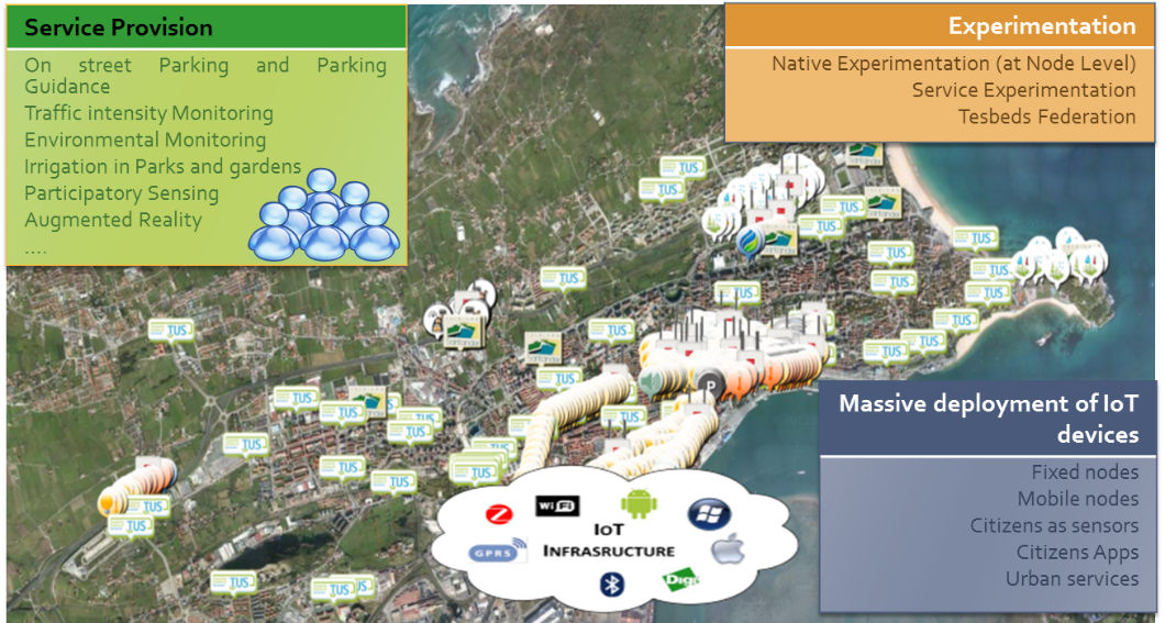
Figure 1. Santander city deloyment

The deployment (shown in Figure 1) associates to the development of different use cases within the project, as described next:

  • Static Environmental Monitoring: Around 2000 IoT devices installed (mainly at the city centre), at streetlamps and facades, are provided with different sensors which offer measurements on different environmental parameters, such as temperature, CO, noise and luminosity. All these devices are provided with two independent IEEE 802.15.4 modules, one running the Digimesh protocol (proprietary routing protocol) intended for service provision (environmental measurements) as well as network management data transmission, whilst the other one (that implements a native 802.15.4 interface) associated to data retrieved from experimentation issues.
  • Mobile Environmental Monitoring: In order to extend the aforementioned static environmental monitoring use case, apart from measuring parameters at static points, 150 devices located at public vehicles (buses, taxis) retrieve environmental parameters associated to determined parts of the city. Modules installed in the vehicles are composed of a local processing unit in charge of sending (through a GPRS interface) the values (geolocated) retrieved by both sensor board and CAN-Bus module. Sensor board measures different environmental parameters, such as, CO, NO2, O3, particulate matters, temperature and humidity, whilst CAN-Bus module takes main parameters associated to the vehicle, retrieved by the CAN-Bus, such as position, altitude, speed, course and odometer. Furthermore, an additional 802.15.4 interface is also included in order to carry out experimentation, interacting with aforementioned static devices, the so called vehicle to infrastructure (V2I) communication.
  • Parks and gardens irrigation: Around 50 devices have been deployed in two green zones of the city, to monitor irrigation-related parameters, such as moisture temperature and humidity, pluviometer, anemometer, solar radiation, pressure and humidity, in order to make irrigation as efficient as possible. In terms of processing and communication issues, these nodes are same to those deployed for static environmental monitoring, implementing two independent IEEE802.15.4 communication interfaces.
  • Outdoor parking area management: Almost 400 parking sensors (based on ferromagnetic technology), buried under the asphalt have been installed at main parking areas of the city center, in order to detect parking sites availability in these zones.
  • Guidance to free parking lots: Taking information retrieved by the deployed parking sensors, 10 panels located at the main streets’ intersections have been installed in order to guide drivers towards the available parking lots.
  • Traffic Intensity Monitoring: Around 60 devices located at the main entrances of the city of Santander have been deployed to measure main traffic parameters, such as traffic volumes, road occupancy, vehicle speed or queue length.

As it can be derived from the described use cases, all of them are intended to provide a different service, as well as offering the retrieved data for other users to experiment with, the so called experimentation at service level.

SmartSantander experiment-driven testbed

Additionally to the experimentation at service level, some of the nodes that take part of the deployment, in particular those supporting static and mobile environmental monitoring and parks and gardens irrigation services (previously described), also offer the possibility of carrying out experimentation at node level.

With experimentation at node level, it is considering that some of the deployed IoT nodes (those previously indicated) can be flashed, as many times as required with different experiments, through OTAP (over-the-air programming) or MOTAP (Multihop OTAP), for nodes more than one hop away from the gateway. In this sense, researchers can test their own experiments, such as routing protocols, data mining techniques or network coding schemes. This experimentation is made available by using an additional IEEE 802.15.4 transceiver the nodes are provided with, thus isolating data traffic associated to experimentation from the generated by the service provision (static and mobile environmental monitoring and parks and gardens irrigation).

The capability of flashing nodes both mobile and static allows the possibility of implementing experiments including Vehicle to Infrastructure (V2I) communications.

SmartSantander user-oriented facility

Apart from the aforementioned use cases, two citizens-oriented services have been deployed, thus including corresponding applications for Android and IOS operating systems, in order to foster the citizens’ involvement.

  • Augmented Reality: This service includes information about more than 2700 places in the city of Santander, classified in different categories: beaches, parks and gardens, monuments, shops. In order to complement and enrich this service, 2000 RFID tags/QR code labels have been deployed, offering the possibility of “tagging” points of interest (POI) in the city such as touristic POI, shops and public places (parks, squares). In a small scale, the service provides the opportunity to distribute information in the urban environment as location based information.
  • Participatory Sensing: In this scenario, users utilize their mobile phones to send to the SmartSantander platform and in an anonymous way, physical sensing information, e.g. GPS coordinates, compass, environmental data such as noise, temperature. Users can also subscribe to services such as “the pace of the city”, where they can get alerts for specific types of events currently occurring in the city. Users can themselves also report the occurrence of such events, which will subsequently be propagated to other users that are subscribed to the corresponding types of events.

It is important to highlight that, in the same way as aforementioned use cases, information retrieved by these two services is made available to the SmartSantander platform, in order other users to experiment with it (experimentation at service level).

Additionally, just to indicate that these applications are continuously evolving adding new functionalities, serving also as basis for the development of new applications in the context of a smart city.

UC-SmartSantander Lab

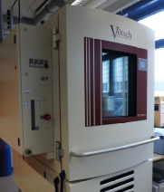
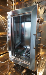
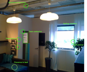
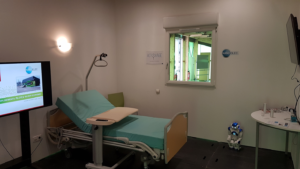
UC-SmartSantander Lab is intended for trying technological IoT and Smart City related solutions in a controlled environment, before carrying out the installation in the different parts of the city.


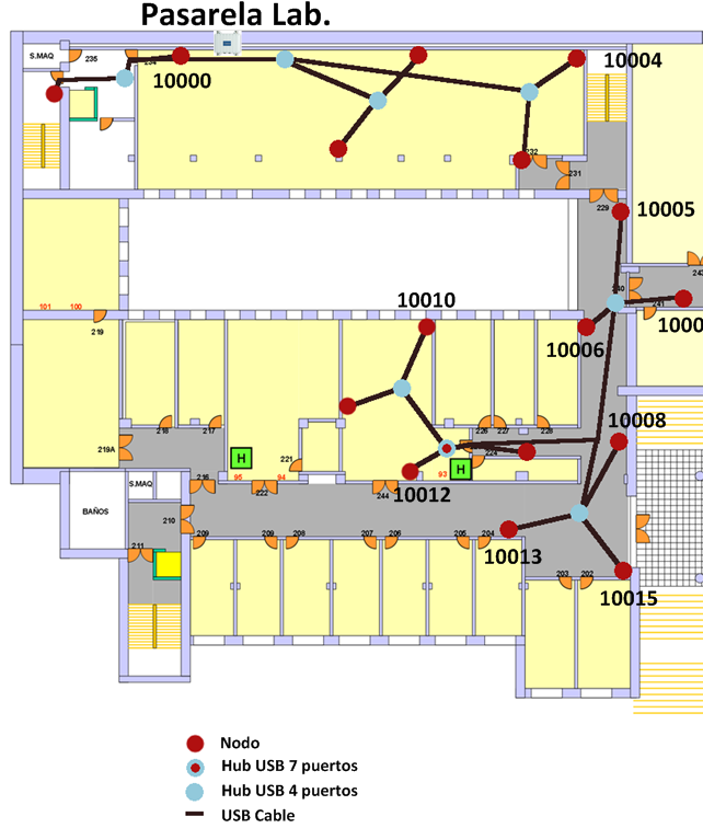
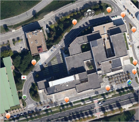
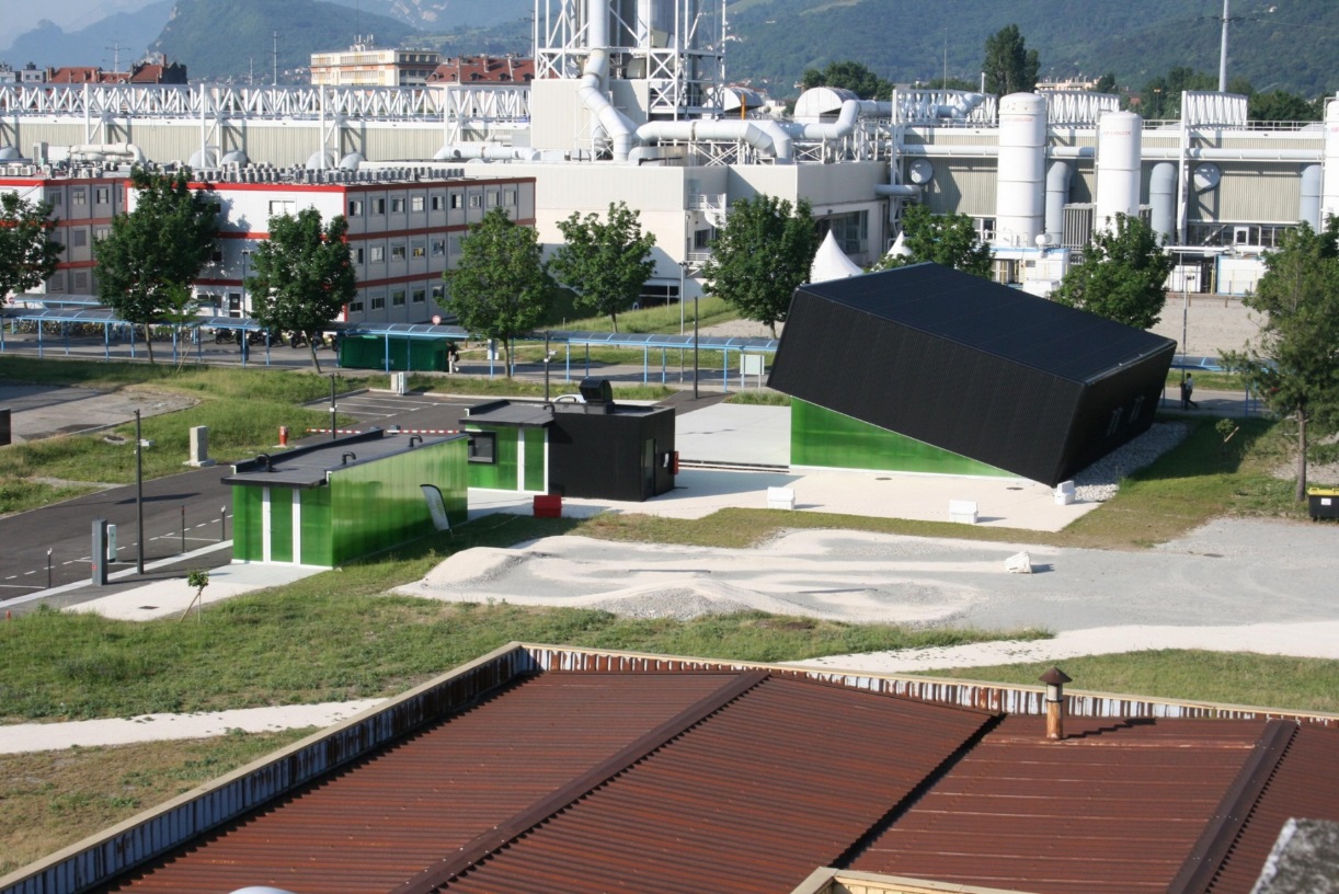
Figure 2. UC-SmartSantander Lab indoor (left) and outdoor (right) deployment

As it can be observed in Figure 2 , on the right side it is presented a replication of city testbed at small scale within UC premises (15 nodes), to test technologies in an accessible indoor environmen. On the left side, it is shown a small outdoor deployment (also around 15 nodes) within University campus for trying developments in a controlled outdoor scenario, prior to install it in the operation scenario..

For further information on the tools, services and assets for developping on top of SmartSantander testbed https://docs.organicity.eu/

Research Concept Vehicle (KTH)

Information

Partner: KTH Stockholm, Sweden
Platform: KTH Research Concept Vehicle
Contact: Mikael Nybacka
Email: mnybacka@kth.se

Open platforms for research, demonstration and education in sustainable transportation – the KTH Research Concept Vehicle

KTH provides open platforms for research, demonstration and education in sustainable transportation, specifically for connected and autonomous transport. The work is led by the KTH Integrated Research Transport Lab (ITRL). We here focus on the KTH Research Concept Vehicle (RCV), see Fig. 1.

The RCV constitutes an open (available designs), evolving and experimental platform (it is used for experiments by KTH researchers and with partners). Past activities for the RCV include participation in the Grand Cooperative Driving Challenge, applications of fault tolerant control, sensor based autonomous driving in on-road and parking scenarios, remote driving with haptic feedback to driving simulator seat, and energy efficient control strategies using over-actuation. The RCV exists in two versions; the basic RCV as depicted in Fig. 1, and the RCV-E, as depicted in Fig. 2.

The RCV-E represents a modified version of the basic RCV, developed by KTH and Ericsson in collaboration. The RCV-E is designed for Connected and Automated Transport with a suitable size for first and last mile type of vehicles. It is equipped with 5G connectivity, has essentially the same actuation as the basic RCV with more powerful in-wheel motors, but with no camber actuation.

What are typical use cases?

A number of usage cases are relevant for the RCV, including (but not limited to):

  • Evaluation of sensor technologies, algorithms and/or computing platforms,
  • Evaluating strategies or specific scenarios for automated driving
  • Remote driving scenarios (RCV-E)

Current work in progress at KTH includes integrating multiple planners for higher automation levels, safe maneuvers (actions at e.g. sensor failure), and semantic segmentation of sensor input.

Further planned activities include motion planning for autonomous parking, utilizing four wheel steering (short term) and deployment and evaluation of dependable computing platforms.

How easy is it to use it and what about gaining access?

Software oriented experiments can easily be integrated in the ROS environment (open source) or through dSpace Autobox. For instance, any sensor that speaks Ethernet or CAN should be relatively easy to integrate. The hardware design is modular and can also be altered with relative ease, as long as there is coordination with other activities

Access to the RCV will be granted according to agreement with KTH, depending on nature of experiments. KTH currently has 2-3 RCV’s at disposal. The access will also depend on the planning of other activities and experiments.

Regarding tests and data collection, we have access to a relatively nearby test track at Arlanda (some 60 km’s from KTH). For tests requiring 5G infrastructure, we have access to the Connected Mobility Arena in Kista (just north of Stockholm). Specific agreement with Ericsson is needed for such tests. A further option is to make use of the AstaZero test facility (however this is much further away, Gothenburg area) and requires separate funding.

Where can I find more information?

Further information about the RCV is available here:

Contacts

Lorawan LPWan (DigiCat)

Information

Partner: Digital Catapult, London, UK.
Platform: Lorawan LPWAN Testbed
Contact: Ana-Maria Gheorghe
E-mail: ana.gheorghe@digicatapult.org.uk

Testbed: Lorawan LPWAN Testbed

LPWANs are wireless network technologies which are particularly suitable for remote sensing applications where battery powered, low bit rate, long range bi-directional secure communications are preferred over traditional cellular communication technologies.

Digital Catapult offers an innovation support programme to accelerate the development of LPWAN based solutions called Things Connected. The Things Connected programme provides access to a London-wide LoRaWAN network, which consists of 50 LoRaWAN base stations located across London and covers major areas within the M25 boundaries.

LoRaWANs are power-efficient and can connect devices over an area of 10-15 kilometres, with ranges extending up to 50 kilometres in some cases. Digital Catapult will grant successful applicants of Open Calls access to the Things Connected programme. It will assist them in developing and deploying their products or services on top of the LoRaWAN testbed, and enable the designed solutions to be piloted and tested at scale across London.

For more information on Lora:

Click here to add your own text

Smart Home, Health and Transportation (CEA)

Information

Partner: CEA France
Platform: Products and Technologies Living-lab
Contact: Isabelle CHARTIER
Email: Isabelle.chartier@cea.fr
Telephone: (+33)04.38.78.39.81

Products and Technologies Living-Lab

The PTL: Products and Technologies Living-Lab aims to speed up the development and marketing of innovative products integrating advanced microelectronics technologies in emerging and strategic fields of Health, Housing and Transport, through the provision of technology platforms and involved expertise. The challenge of PTL is to develop real environments with technological bricks from the micro and nanoelectronics and offer a range of attractive services for products and services designers. It requires to set-up three technology platforms, from technology and solutions provided by the partners and founders of PTL:

  1. “Connected House” to confront communicating electronic devices and communication networks inside buildings in a real situation of interoperability of current heterogeneous systems. This platform is specifically devoted to energy efficiency and intelligent home control applications. One scenario investigated is especially focused on comfort management and of energy cost efficiency based on control of heating, air conditioning and ambience with sensors connected to heating and cooling system, motion detectors, temperature sensors and smart scheduling systems.
  2. “Connected Transport” to assess the contribution of micro and nanoelectronics in transport especially in vehicles to improve safety and mobility. PTL offers a pluggable stretch of road with street furniture and technical and control rooms. Various scenarios could be played thanks to instrumented crossroads, connected traffic lights and electronic systems. For example, a surveillance installation for monitoring traffic based on variable traffic signs or variable message signs (VMS) to display traffic information and management or lane control could be tested easily. Another situation takes an interest in active and passive park assist systems to help drivers find or reserve a near parking place especially through smart systems connecting cars to the city and visual signs based on totem concept.
  3. “Home Health” to retrieve and merge information from environmental, physiological and activity sensors, and send higher-level information through available communication networks to improve safety, comfort and autonomy. One of the main proofs of concept exhibits an elderly flat instrumented with major communication protocols (KNX, enOcean, Bluetooth, ZigBee…) and middlewares (sensiNact, OpenHab…) to enable interconnection and interoperability of devices and services.

The customers of this service have access to (1) tools and platforms to design their products, (2) testing and simulation resources to assess the relevance of the concepts, the performance of chosen solutions and robustness of their development, and (3) high-level expertise to support identification of technological, strategic and/or statutory constraints and leeway in application sectors of health, transport and housing.

PTL builds, enhances and provides access to sustainable platforms of functional interconnected solutions integrating the technologies provided by partners and founders, in order to facilitate their access and adoption by future users and customers.

The key aim of the PTL is to emerge as a benchmark center for “smart cities”. PTL brings together technological solutions ready to be deployed in the context of large-scale experiments carried by public or private actors.

The strength of the PTL is to provide various large-scale test environments, whether indoors or outdoors with the opportunity to have access to high-tech equipment such as a channel emulator or placing antennas up in these different environments

Field of expertise and market domains

Expertise:

  • IoT and data management
  • Safety and security: hardware security, cybersecurity, privacy management, protection against attacks
  • Interconnection of complex systems, interoperability

Methodologies:

  • Co-conception with all stakeholders of the value chain
  • Functional assessment of IoT system

Application domains:

  • Active and Healthy Ageing
  • Autonomy & Handicap
  • Work and occupational health
  • Smart living, Smart building

Facilites of the mini smart village

A mini smart Village in a secure and closed environment (CEA site) dedicated to experimentation in the fields of Health, Housing and Transport:

  • A room dedicated to experimentation in the fields of Active and Healthy Ageing (AHA), Ageing in place and Building Automation (SILVER LAB Project)
  • A nursing home room (EHPAD like) dedicated to experimentation in the field of Ageing in institution (ACTIVAGE Project)

Communication material

Pitch sentence: Develop innovative products and services, assess and validate their technological performance in realistic environment

Mini smart Village

PTL CEA- IRT Nanoelec testbed : a smart village for IoT services testing

SILVERLAB ROOM

SILVER LAB: Early and automatic detection of functional decline and frailty in the elderly.

  • Activity monitoring & Behavioral models
  • Risk detection (falls, functional decline…)
  • Security for IoT at Home :
  • Communication security (radio)
  • Privacy respect & Personal data confidentiality
  • Usages driven design, development and assessment
  • Business models (Senior residence)

ACTIVAGE NURSING HOME TESTBED

Part of the IoT Large Scale Pilot Focus Area.

Nursing home room with bedroom and bathroom

  • IoT sensors
  • Security
  • IoT PF Interoperability

Services Co-Conception with all stakeholders

  • return home safely after an hospitalization
  • improve comfort and safety in care facility
  • improve professional caregivers actions efficiency

Links

IRT Nanoelec: http://www.irtnanoelec.fr/pulse/

Part of the EIT HEALTH Living Lab Network: https://eithealth.eu/

Activage Project: http://www.activageproject.eu/deployment-sites/Isere/

Contact detail

Isabelle CHARTIER
Grenoble – France
(+33)04.38.78.39.81
Isabelle.chartier@cea.fr
http://www.irtnanoelec.fr/pulse/

Reliability testing capabilities (BME)

Information

Partner: University of Technology and Economics (BME), Budapest, Hungary
Platform: RELIABILITY TESTED
Contact: Professor Márta Rencz
Email: rencz.marta@vik.bme.hu

Testbed Summary

What is VRT?

VRT stands for Versatile Reliability Tester. It can provide reliability data combined with electro-thermal data on smart systems and on its components. Standardized test procedures (temperature cycling with relative humidity control, power cycling) can be customized for sensors, actuators, drivers or even for complete smart objects with command and control units.

Possible Applicartions

Safety-critical systems, life-time modelling, physics-of-failure evaluation, critical failure mode identification, aiding device health monitoring, aging indicator identification

Benefits

  • Expectations can be met both from the designer and from the end-user side
  • Harsh environment performance can be tested even during design state
  • Minimizing on-site failures that cost time, money and reputation
  • Burn-in or run-in procedures could be done in one step with reliability testing
  • Maintenance could be scheduled, optimizable warranty and spare part availability
  • Minimizing safety risk, understanding conditions leading to failure or injury

Challenges

  • Identifying the standards to meet in inter-discipliner fields of applications is not always easy
  • Difference between artificial harsh environment and real life applications should be taken into account with appropriate acceleration factors that translate the test duration to effective life-span

External references

Commonly used life testing standards

System overview

  • The reliability test environment at BME integrates a set of appropriate hardware and software components built around the de facto industry standard T3Ster equipment of Mentor Graphics. The system monitors the electric, thermal and even optical parameters of the device under test during freely customizable test sequences.
  • The core of the system is the Main Control Box (1). It is responsible for the control of the external hardware components, for the signal conditionings of the DUTs and for the measurement data storage.
  • In the actual configuration (as shown) a Mentor Graphics T3Ster Thermal Transient Tester (2), an Agilent N5770A power supply unit (3), a Mentor Graphics HV10V100 power booster (4), a Julabo F25-MC refrigerated/heating circulator (8) and a Weiss WK3-340/70 climate chamber (9) are connected externally. The DUTs (6) are mounted onto a coldplate (7) in the displayed setup.
  • Between the DUTs and the coldplate, customized sample holders can be mounted for further measurement system attachment. The user interface (5) and control of certain (less critical) processes are served by the embedded computer of the Main Control Box.

Figure 1: Photo of the reliability test environment at BME

Full Details of the Testbed

Reliability and lifetime prediction of cyber physical systems is getting into focus as safety critical applications starting to involve such platforms. With the increasing hardware integration of smart systems, dissipated power density also gets bigger. As computer performance is on a rise both in commercial and industrial applications, every year the challenge is getting bigger for the manufacturers to increase the performance per watt of their devices without sacrificing reliability. Also, the designers have to develop new cooling solutions facing the high power dissipation of such devices, and reliable bonding techniques. Thermal-aware design and selecting the proper packaging structure for the application is mandatory to avoid premature failures. At the stage of product development, it is truly vital to have data on the estimated lifetime of the components in certain applications. Input for such prediction techniques could be acquired from the reliability test facility that BME has developed.

The reliability test environment integrates a set of appropriate hardware and software components built around the de facto industry standard T3Ster equipment of Mentor Graphics. This versatile system monitors the electric, thermal and even optical parameters of the device under test during freely customizable test sequences.

The core of the system is the Main Control Box (1). It is responsible for the control of the external hardware components, for the signal conditionings of the DUTs and for the measurement data storage. In the actual configuration (as shown on Figure 1) a Mentor Graphics T3Ster transient tester (2), an Agilent N5770A power supply unit (3), a Mentor Graphics HV10V100 power booster (4), a Julabo F25-MC refrigerated/heating circulator (8) and a Weiss WK3-340/70 climate chamber (9) are connected externally. The DUTs (6) are mounted onto a coldplate (7) in the displayed setup. Between the DUTs and the coldplate, special sample holders can be mounted for further measurement system attachment. The user interface (5) and control of certain (less critical) processes are served by the embedded PC of the Main Control Box.

The system was designed for flexible operation in various reliability testing environments, especially for long term power, temperature or relative humidity cycling beyond storage test. As the related tests could last for several weeks, special requirements have to be fulfilled. The system has to operate continuously, even in case of test environment rearrangement or temporal failures in the measurement equipment used for monitoring the relevant characteristics of the devices under test. The operation of the test system has to be independent of the physical nature of the sample sets and it should be possible to define different timing and powering schemes during the active cycling. The system has to operate smoothly, without interruption at sample change or fault. In the framework of the NANOTHERM project such a reliability tester was developed to meet these requirements and to serve as a low and medium power laboratory test environment, ideal to carry out final reliability tests on up from component level (sensors, drivers, LEDs, FETs, etc) to project demonstrators.

For more information, please contact

Professor Márta Rencz:

H-1117 Budapest, Hungary

Email: rencz.marta@vik.bme.hu