Information

| Partner: | University of Technology and Economics (BME), Budapest, Hungary |
| Platform: | RELIABILITY TESTED |
| Contact: | Professor Márta Rencz |
| Email: | rencz.marta@vik.bme.hu |
Testbed Summary
What is VRT?
VRT stands for Versatile Reliability Tester. It can provide reliability data combined with electro-thermal data on smart systems and on its components. Standardized test procedures (temperature cycling with relative humidity control, power cycling) can be customized for sensors, actuators, drivers or even for complete smart objects with command and control units.
Possible Applicartions
Safety-critical systems, life-time modelling, physics-of-failure evaluation, critical failure mode identification, aiding device health monitoring, aging indicator identification
Benefits
- Expectations can be met both from the designer and from the end-user side
- Harsh environment performance can be tested even during design state
- Minimizing on-site failures that cost time, money and reputation
- Burn-in or run-in procedures could be done in one step with reliability testing
- Maintenance could be scheduled, optimizable warranty and spare part availability
- Minimizing safety risk, understanding conditions leading to failure or injury
Challenges
- Identifying the standards to meet in inter-discipliner fields of applications is not always easy
- Difference between artificial harsh environment and real life applications should be taken into account with appropriate acceleration factors that translate the test duration to effective life-span
External references
Commonly used life testing standards
- Temperature cycling: https://www.jedec.org/standards-documents/docs/jesd-22-a104e
- High temperature storage: https://www.jedec.org/standards-documents/docs/jesd-22-a103d
System overview
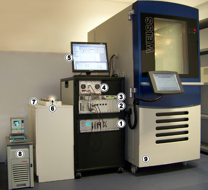
- The reliability test environment at BME integrates a set of appropriate hardware and software components built around the de facto industry standard T3Ster equipment of Mentor Graphics. The system monitors the electric, thermal and even optical parameters of the device under test during freely customizable test sequences.
- The core of the system is the Main Control Box (1). It is responsible for the control of the external hardware components, for the signal conditionings of the DUTs and for the measurement data storage.
- In the actual configuration (as shown) a Mentor Graphics T3Ster Thermal Transient Tester (2), an Agilent N5770A power supply unit (3), a Mentor Graphics HV10V100 power booster (4), a Julabo F25-MC refrigerated/heating circulator (8) and a Weiss WK3-340/70 climate chamber (9) are connected externally. The DUTs (6) are mounted onto a coldplate (7) in the displayed setup.
- Between the DUTs and the coldplate, customized sample holders can be mounted for further measurement system attachment. The user interface (5) and control of certain (less critical) processes are served by the embedded computer of the Main Control Box.

Figure 1: Photo of the reliability test environment at BME
Full Details of the Testbed
Reliability and lifetime prediction of cyber physical systems is getting into focus as safety critical applications starting to involve such platforms. With the increasing hardware integration of smart systems, dissipated power density also gets bigger. As computer performance is on a rise both in commercial and industrial applications, every year the challenge is getting bigger for the manufacturers to increase the performance per watt of their devices without sacrificing reliability. Also, the designers have to develop new cooling solutions facing the high power dissipation of such devices, and reliable bonding techniques. Thermal-aware design and selecting the proper packaging structure for the application is mandatory to avoid premature failures. At the stage of product development, it is truly vital to have data on the estimated lifetime of the components in certain applications. Input for such prediction techniques could be acquired from the reliability test facility that BME has developed.
The reliability test environment integrates a set of appropriate hardware and software components built around the de facto industry standard T3Ster equipment of Mentor Graphics. This versatile system monitors the electric, thermal and even optical parameters of the device under test during freely customizable test sequences.
The core of the system is the Main Control Box (1). It is responsible for the control of the external hardware components, for the signal conditionings of the DUTs and for the measurement data storage. In the actual configuration (as shown on Figure 1) a Mentor Graphics T3Ster transient tester (2), an Agilent N5770A power supply unit (3), a Mentor Graphics HV10V100 power booster (4), a Julabo F25-MC refrigerated/heating circulator (8) and a Weiss WK3-340/70 climate chamber (9) are connected externally. The DUTs (6) are mounted onto a coldplate (7) in the displayed setup. Between the DUTs and the coldplate, special sample holders can be mounted for further measurement system attachment. The user interface (5) and control of certain (less critical) processes are served by the embedded PC of the Main Control Box.
The system was designed for flexible operation in various reliability testing environments, especially for long term power, temperature or relative humidity cycling beyond storage test. As the related tests could last for several weeks, special requirements have to be fulfilled. The system has to operate continuously, even in case of test environment rearrangement or temporal failures in the measurement equipment used for monitoring the relevant characteristics of the devices under test. The operation of the test system has to be independent of the physical nature of the sample sets and it should be possible to define different timing and powering schemes during the active cycling. The system has to operate smoothly, without interruption at sample change or fault. In the framework of the NANOTHERM project such a reliability tester was developed to meet these requirements and to serve as a low and medium power laboratory test environment, ideal to carry out final reliability tests on up from component level (sensors, drivers, LEDs, FETs, etc) to project demonstrators.
For more information, please contact
Professor Márta Rencz:
H-1117 Budapest, Hungary
Email: rencz.marta@vik.bme.hu

